Description
Knowles DLI brand Cavity Resonators provide an ideal solution for high performance, low-cost microwave, or millimeter wave oscillators. The patented high-Q cavity resonator devices are fully shielded and designed on our temperature stable, high dielectric constant ceramics.
An equivalent circuit modeling tool was developed that enables optimization of resonator based oscillator designs and constrains circuit element values to realizable combinations. Below are example models at 8 GHz. Two models are shown using CF ceramic, one using FS, and one using CG.
Frequencies of resonator designs range from <1.0 to >67 GHz and can be customized for either solder-surface mount or chip and wire applications. High reliability thin film gold metallization is employed and frequency tolerances as low as 0.1% are attainable.
Applications
Systems: Circuits
Automotive: Microwave & Millimeter-Wave Oscillators
Radar: Fundamental Fixed Frequency Oscillators-Ultra-low Phase Noise (former solution: expensive DRO's and multiplied-up crystal or SAW based device with decreased performane)
Communications: Narrow-Band Tunable VCO or Phase Locked Oscillators (typically ± 3% tuning)(former solution: varactor tuned expensive DRO)
Military: Integration of high performance Oscillators directly on the system motherboard without the expense and complexity of sub assemblies, housing and labor intensive operations typical of former solutions.
Instrumentation: Narrow bandwidth low loss filters (former solution: low loss SAW devices with frequency limitation and poor performance)
Single Frequency Cavity Resonators
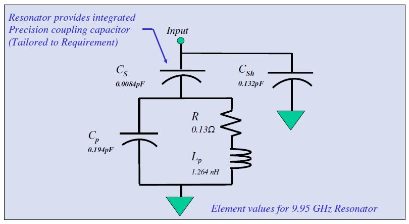
The equivalent circuit of the Single Frequency Cavity Resonator (SFCR) near its lowest resonat frequency is shown. The lowest resonat mode is typically employed in oscillator and filter designs. The element values are shown for a 9.95 GHz SFCR. The resonat frequency is set by the parallel combination of Cp and Lp, the finite unloaded Q by R. The series capacitance Cs connects the resonator L-C to the input pad, thus setting the coupling between the external circuit and the frequecny controlling L-C resonator. The capacitance Csh is a stray capacitance between the input and and ground. All of these netweork elements have excellent repeatability providing thight control over resonat frequency, coupling and input impedance. The structure also provides an integrated DC blocking function, thus eliminationg a tolerance sensitive element from the bill of materials. For wide bandwidth circuit modeling, S-Parameters are recommended. S-Parameters are available for downloading (LINK). The resonators are redily customized for frequency, coupling, Q, tunability and assembly requirements.
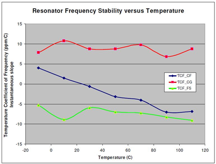
This graph depicts typical SFCR frequency stability versus temperature for Knowles DLI brand standard dielectric materials.
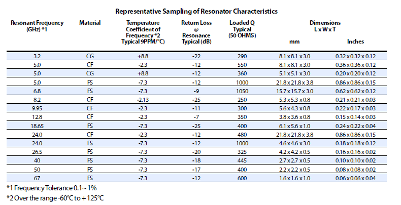
A sampling of representative SFCR characteristics is shown in the below table to illustrate the primary resonator design variables (frequency of resonance, cavity material dielectric constant, length-by-width dimensions). The interaction of these variables is discussed in further detail in a later section. The loaded Q of the resonators is affected by the coupling coefficient (denoted in the tables in terms of return loss), the material choice (dielectric constant), and by material thickness. Generally, resonators made from thick, low dielectric constant materials are capable of the highest loaded Q’s. For reference, when a resonator has a coupling coefficient of 1.0, it will exhibit an excellent return loss at the resonat frequency and the unloaded Q will be 2 times the loaded Q value. The desired level of resonator coupling varies with individual circuit requirements such as varactor frequency tuning or transistor negative resistance value. The unloaded Q‘s of the cases shown range up to 2,000, clearly a new standard for a component compatible with automated assembly. In contrast to other ‘high QW’ microwave resonators, Knowles DLI brand cavity resonator is completely self-contained. Large, expensive housings are not needed. It’s loaded Q and resonant frequency can be directly measured using RF coplanar probe technology. Thus, ambiguities of special test fixtures and components which are not appropriate to the product realization are eliminated from part evaluation.
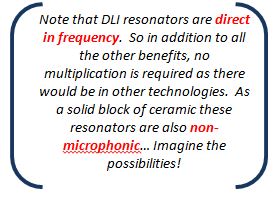
- Eliminate lage, expensive housings
- Measured using RF coplanar probes- no fixtures necessary
- Automated assembly
- Q's up to 2000
Estimating Resonator Size
The size of the cavity resonator is determined by the desired resonat frequency and the ceramic material selected. At the same resonat frequency, a higher dielectric constant material will offer reduced size compared to a lower dielectric constant material. Resonators are typically designed on thick ceramics doe to Q increasing with material thickness. The below charts can be used as a guide for estimating resonator sizes on typical DLI materials. Designs are slightly rectangular in shape. Length to width aspect rations are usually less than 1.2:1. For additional information consult the factory.
Tuning SFCR’s
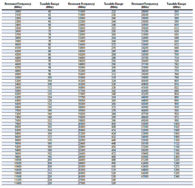
Knowles DLI brand has the ability to laser trim down the frequency of a cavity resonator by approximately 2% of the actual resonat frequency. The resonators incorporate lithography defined ‘snake eyes’ that the laser can recognize as a starting point to trim through the gold. Frequencies above and below this range are obtainable. The table below shows a matrix of resonat frequencies and their tunable range.
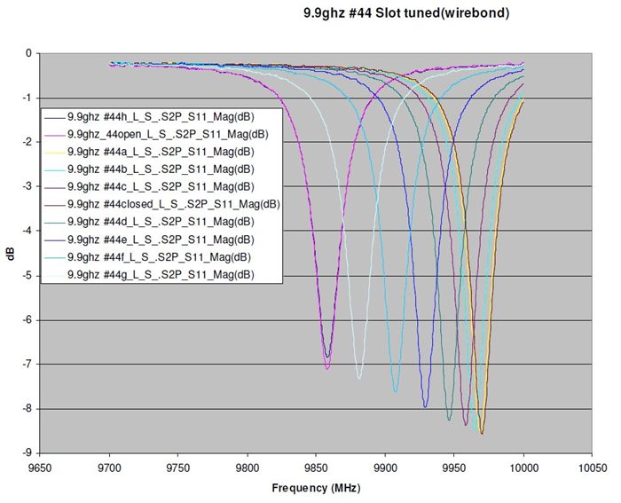
The graph below shows a 9.9 GHz resonator that was tuned down in frequency by laser trimming slots through the gold metallization. In this particular example the part was lasered approximately 96 MHz lower than its true resonate frequency (1%). Tuning resonators up in frequency is possible by using photo lithography to define slots on the top side of the resonator circuit. Wire bonding across the slots will tune the device up in frequency.
Mounting Alternatives
Please see our application note which goes into detail on the two different methods of mounting SFCR’s.