Design Guidelines: Resistors
Many sheet resistivities are available to the designer. The selection should be left to the factory when possible to maximize yield and reduce cost. When sheet resistivities must be specified, the overall range and tolerance requirements must be balanced to obtain the optimum choice for processing. Resistor tolerances of ±10% usually require trimming, although some designs can achieve ±5% without trimming. Resistor tolerances of less than ±2% will affect manufacturing yield in volume. For resistor tolerances ≤ 1%, please contact the factory for further design considerations to optimize yield.
1000 Hour @125°C Typical Resistor Data
|
AI2O3,AIN
|
TaN2
|
-125±25
|
25-150
|
<0.5%
|
|
AI2O3
|
NiCr**
|
0-25
|
50-250
|
<0.5%
|
Note: All Tests are performed in forced air convection
furnaces on un-trimmed resistors.
**Proprietary Alloy
Resistor Design and Layout Criteria*
|
|
± .0005"
|
|
Resistor Length
|
.002"
|
|
Resistor Width
|
.002"
|
|
Termination Length
|
.003"
|
|
Termination Width
|
.003"
|
|
Resistor masking overlay on conductor termination
|
.002"
|
|
Resistor inboard of conductor
|
.0005"
|
*Note: Resistor inboard of conductor
termination only
Resistor Trimming Styles
|
Bake to Value
|
±10% STD,
±5% Special
|
Resistors must be optimized for manufacturability
|
|
|
1-10%
|
Design to Accommodate 50% width reduction
|
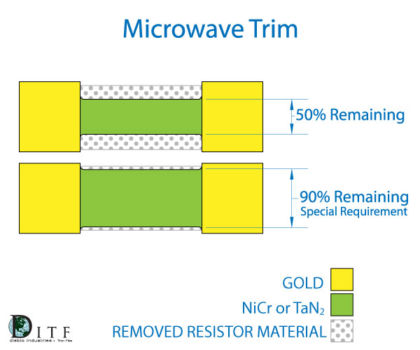 (Symmetrical Scan Cut) |
1-10%
|
Design to Accommodate 50% width reduction 10% Reduction by Request
|
|
|
1-10%
|
Compensate Resistor width to accommodate laser kerfs of .0015" for Each plunge
|
*Note: A test structure can be used to monitor
shorted or isolated resistors.
Helpful Formula:
|
R1 = Initial Resistance (Ω)
R2 = Final Resistance(Ω)
T1 = Initial Temperature (°C)
T2 = Final Temperature (°C)
|