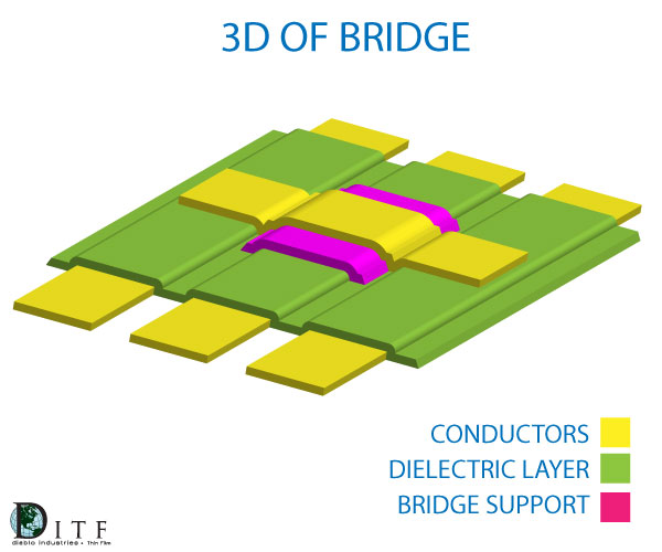
Design Guidelines: Supported Bridges
An integral part of any circuit design are couplers (including Lange couplers) and spiral inductors. These structures can be a challenge to the assembly process and a source of common damage during manufacturing and testing. Wire bonding these features also introduces inconsistency in the design which can result in more tuning and variability, especially over broad frequency ranges. Long an industry standard, we offer supported bridges—a consistent, reliable way to incorporate these structures. We can also test these features to ensure performance prior to integrating high cost active devices.
Fine Line Conductor Standard Layout Guidelines
Line Spacing

|
.0004" minimum ± .0001"
|
Minimum space width available in TiW films only
|
Line Width
|
.0005" minimum ± .0001"
|
Minimum line width available in TiW films only
|
|
|
.001" minimum
|
.0001" Bridge/Conductor Pullback
|
|
|
.001" square minimum
|
|
|
|
.003" minimum
|
|
|
|
.0015" x .003"
|
.0025" overlap, insulator to conductor
|
|
|
width + .006", span + .008"
|
may be deleted at factories discretion on small bridges
|
Bridge Height
|
200 microinches minimum
|
250 ±50 microinches typical
|
Bridge Thickness
|
250 microinches minimum
|
300 ± 50 microinches typical
|
Span Width
|
6:1 maximum
|
|